MF2007SW
Application Note
Overview/Features
MF2007SW is an IC designed to drive external N-channel MOSFETs.
This section presents two typical examples of its use.
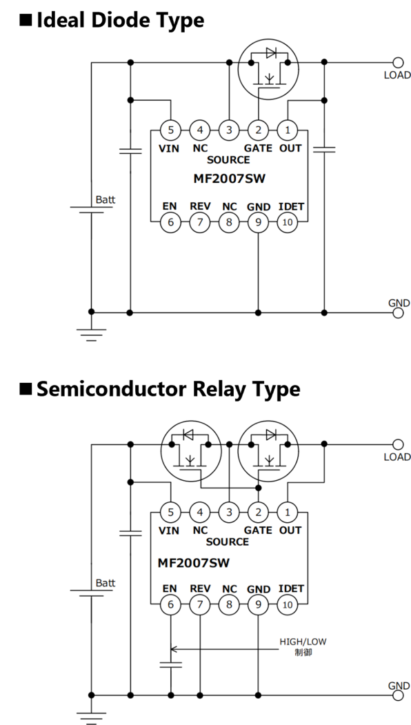
Ideal diode (always on) type
ECU uses the output from a battery or DC/DC converter as an input source. Typically, diodes are used as input reverse connection and reverse current prevention elements. However, as electronic devices have become multifunctional, thereby requiring larger currents, concerns have emerged about increased voltage drops (VF) and heat buildup of diodes. Replacing these conventional diodes, a configuration of “one N-channel MOSFET + MF2007SW” can serve as an ideal diode that achieves low VF and low heat buildup.
Solid state relay (bidirectionally conducting on-off switch) type
Mechanical relays have conventionally been used as bidirectional on-off switches. Bidirectional switches are now required to be small and lightweight. A configuration of “two N-channel MOSFETs + MF2007SW,” smaller and more lightweight than a mechanical relay, can serve as a solid state relay that provides reliable on-off switching and quick response.
■ The reverse current prevention function is enabled or disabled by the high-low control of the REV pin.
■ Maximum input rating: 70V
■ Standby current: 5μA (* This is the current flowing into the IC when shutdown is initiated by turning the EN pin low.)
■ Gate voltage (charge pump voltage): 12.5V
■ Gate charging current: 75μA
■ Gate discharge current at fast charging initiated by reverse current detection:0.7A (typ)
■ Gate discharge current at fast charging with EN = low:0.12A (typ)
■ Incorporates a built-in capacitor for charge pump; requires no external capacitor.
■ Monitors potential differences between the drain and the source of an external N-channel MOSFET (VDS monitoring function);
enables shutdown in the event of an abnormality using the IDET pin, which outputs analog signals based on the monitored potential differences.
■ Protected against input reverse connection up to 40V
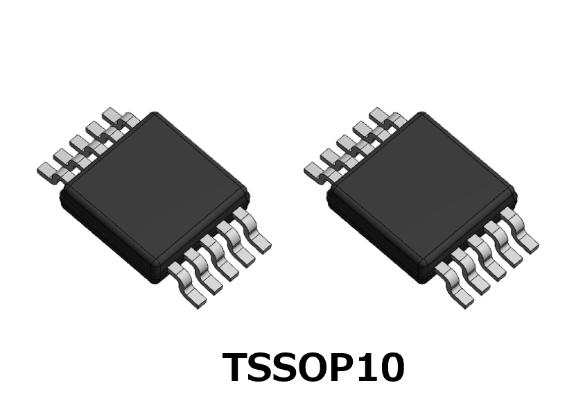
■ Enables smaller device dimensions by adopting a small SMD package (TSSOP10:3mm×4.9mm).
■ AEC-Q100 compliant
Ideal diode type
■ VF (voltage drop), loss and heat buildup are significantly reduced compared to a Schottky barrier diode.
■ If the reverse current comparator detects a reverse current, Gate fast discharge function (0.7A) is activated to turn off the external N-channel MOSFET.
Solid state relay type
■ Smaller in size, more lightweight and quicker in response as well as enabling on-off operation with less chattering than mechanical relays.
■ If an abnormal operation is detected, the EN pin is driven low, which activates Gate fast discharge function (0.12A) and immediately stops operation.
Application Note Contents
1. Overview
1.1 Features
1.2 Basic connection examples
1.3 Block diagram
1.4 Pin assignment and functions
1.5 Appearance and dimensions (package: TSSOP10)
1.6 Land pattern example
2. Specifications
2.1 Absolute maximum ratings
2.2 Recommended operating conditions
2.3 Electrical characteristics
3. Functions and electrical characteristics of individual pins
3.1 VIN pin
3.2 EN pin
3.3 Gate pin
3.4 Source pin
3.5 Out pin
3.6 IDET pin
3.7 REV pin
3.8 GND pin
4. Circuit operations and functions
4.1 Basic operations
4.2 Normal start and stop
4.3 On-off driving of external N-channel MOSFET
4.4 Gate fast discharge function
4.5 Reverse current prevention function
4.6 VDS monitoring function
4.7 Countermeasures against input reverse connection up to 40V
4.8 IC current consumption
5. Method for selecting peripheral component constants
5.1 N-channel MOSFET
5.2 VIN pin capacitor and Out pin capacitor
5.3 EN pin capacitor and REV pin capacitor
5.4 IDET circuit
5.5 External protection components
5.5.1 Input surge protection
5.5.2 Countermeasure against negative output voltages
5.5.3 Gate protection
6. Application circuit examples
6.1 Ideal diode connected in parallel
6.2 Bidirectionally conducting solid state relay
7. Pattern layout
7.1 Pattern layout examples
Example Circuits
| Terms and Conditions for Licensing of Application Note |
|
Upon downloading Application Note, you will be considered as having given your consent to the content of this Agreement. |
|